Initial idea
When we started to play with our recently acquired RC cars, Benoit's kids wanted to try them. Unfortunately the cars are too powerful and too fast for kids, they can really be dangerous for them, and they can break them, so they were a bit frustrated by our refusals.This led me to realize that such devices are missing a "training mode". I thought that maybe it would be possible to implement a speed limiter using an ATTINY microcontroller. After a bit of thinking, in fact it's really easy, considering that :
- pulses are supposed to be 500 to 2500 microseconds long
- pulses are 20 ms apart
- accuracy is not a big deal for forward/backward speed
- the signals are <= 5V amplitude
- the 0 and 5V are present on the pulse cable
- wait for a pulse
- measure the pulse width
- perform whatever computation needed, for less than 15 ms
- emit a new pulse
Timing
The first important point is to be able to measure a pulse width and to create a pulse. We don't have a very high frequency so we want to waste the least possible cycles counting. I tried several constructs for a loop and ended up with 5 cycles per loop to measure a pulse, giving a resolution of +/- 0.625 microseconds at 8 MHz (ATTINY85) and +/- 0.52 microsecond at 9.6 MHz (ATTINY13A). The code looks like this, with width giving the pulse width in CPU cycles :uint16_t width = 0;
while (!(PINB & (1 << PB2))); // wait for beginning of pulse on PB2
while (PINB & (1 << PB2)) // wait for end of pulse
width += 5;
To create a pulse, you need to wait for some time. Usually this is done using a volatile integer but here I noticed that it made gcc produce very poor quality code resulting in 14 cycles being spent per loop. Instead I used a barrier made of an empty asm statement that gcc couldn't optimize away. This resulted in only 4 cycles being spent per loop, which is much better :
PORTB |= 1 << PB3; // start pulse
while (--width) asm volatile("");     // wait width*4 cycles
PORTB &= ~(1 << PB3);       // end pulse
The width can be converted to microseconds by multiplying/dividing it by the CPU's frequency. Care must be taken to avoid integer overflows while sticking to 16 bits. For integral MHz frequencies it's trivial. For non-integral MHz frequencies, the conversion can be done on 32 bit while keeping 16 bit values in and out.
With only this done, we don't need the C++ nor arduino environment anymore and we can have a very compact C code.
Scaling pulses
I did a first scaling attempt by dividing the distance to the center by two. Given that the center is 1500 microseconds, the pseudo-code looks like this :int16t width;
width = read_pulse() - 1500; <0 = rear; >0 = front
width /= 2;
send_pulse(width + 1500);
It worked pretty well but I realized that I couldn't brake anymore by going backwards. In fact my car brakes before trying to go backward when it was going forward, and the braking force depends on how far I pull the trigger. Not being able to brake is not acceptable, so I had to implement the whole ESC's state machine.
State machine
I ran some tests and noticed the following :- at rest (initialization), the car can go backward
- at rest, the car can go forward
- when going forward and suddenly backward, it brakes
- the car continues to brake until the trigger is released. In order to go backward, I have to release it and pull it again. This means that after braking and releasing the trigger, it goes to rest again.
- if I only release the trigger when it's going forward, braking is possible for the first 2.5 seconds. Waiting longer will make it go backward. This means that after 2.5 seconds not accelerating it goes back to the rest position
- it I pull the trigger again to go forward while braking it goes forward again
- if I pull the trigger forward when it goes backward, it goes forward immediately
I ended up implementing the following state machine :
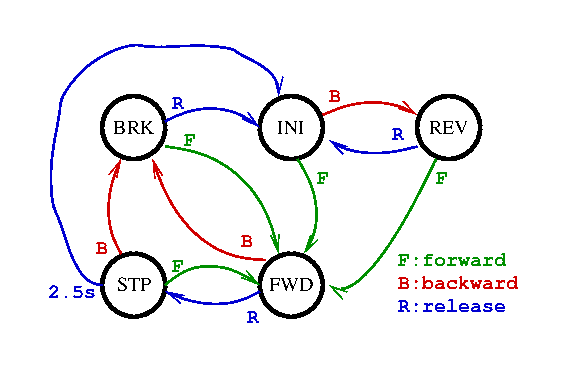
This state machine allows a different ratio to be applied to different states. The forward and backward speeds are cut in half, but the brake force is kept at full scale.
I found that the car was lacking a bit of "punchiness" when starting up, so I modified the FWD state to allow it to reach full speed for the first 300 ms. This allows it to deploy the full force to the wheels to make it drift and perform a U-turn for example, or to accelerate very quickly from rest, without permitting it to reach a high speed. In fact it even starts to become fun :-)
I also realized that knowing the current state makes it convenient to light some LEDs to indicate what is being done. We can have a set of brake lights made of red LEDs, and a backward light made of a white LED.
Centering
I found that the internal RC oscillator is not very precise so I implemented an automatic frequency adjustment at boot so that the car would not automatically start to advance or go backward. The idea is that when booting, the only signal we're supposed to see is the center position, so we average it over a few measures and compute the offset so that this one equals 1500 microseconds. This state is implemented at boot before going to the INI state.Also the LED on PB1 (pin 6) which is present on some ATTINY85 boards is used as a debugging indicator. It is lit when we're not at the rest position. This eases centering on the transmitter because the led must be turned off by default.
Implementing the basic ON/OFF switch
Just similar to what was implemented from a disassembled servo a few months ago, it's possible to implement an RC switch from this controller by enabling/disabling a GPIO depending on the pulse width. So I added such a very simple test to connect to an output pin. After I realized that by implementing this on a $0.30 ATTINY13A, coupled with a $0.07 cable it could be 3 times cheaper than the previous solution, I ended up writing a simplified version of the program doing just that, called onoff.c. But the same function was implemented on its own pin on the main program so that pre-programmed chips can be use for both purposes without having to be reprogrammed.Multiplexing LEDs
ATTINY13/85 only have 5 usable GPIO (well 6 if you reprogram the RST pin but I don't want to, it's too painful for development). With one GPIO for the input pulse, one for the output pulse, one for the centering LED, one for the ON/OFF LED, it leaves only one pin for the brake/rear LEDs. However there's a solution to solve this. If we put 2 red LEDs and 1 white LED in series, their total voltage is around 6.6V so they will not turn on on 5V. However it's possible to light either the 2 red ones or the white one by connecting their middle pin to the power supply or ground. The only thing is that to turn them off we need to disconnect the pin, which is equivalent to configuring it for input. It will only keep the internal pull-up which will be too weak to turn the LEDs on. We could use a single resistor connected to the GPIO, but it's safer to use one per set of LED so that in the event an over voltage would appear beyond their turn-on voltage, the drained current remains limited.
Implementation
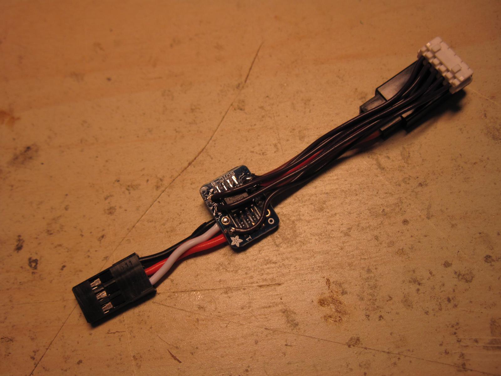
The device was implemented on an SOIC8 ATTINY13A soldered on an SOIC8-do-DIP8 adapter serving as a PCB. The GPIO pins were chosen on opposite sides of the device so that wires could easily be soldered without having to bend them too much :
A simple male-to-female connector was cut to provide both the connector to the RX and the connector to the ESC. An extra 5-pin connector was added to access the LED signals. There is no additional component, only the MCU and cables. All this was enclosed in heat shrink tube and could be placed inside the receiver receptacle in the car.


Improvements
Some improvements could be made. First, I forgot to solder a wire to the RST pin in case I'd want to reprogram the device. Second, it would make sense to support detecting a short-circuit on one of the GPIO at boot in order to disable the throttling. It could result in sort of an adult/kid switch. For example, the debug LED GPIO could be used for this since it's only used to debug the throttling.It would also be nice to try to make the device learn the highest possible speed from the remote, but probably that it is not very easy to implement in that small code. There are only 220 bytes left on the ATTINY13A, so that's something to keep in mind.
Code
The source code is available here. The executables are so small that they can be dumped here. For ATTINY13A, the fuses to use are :- low: 0x7A
- high: 0xFF
- low: 0xC1
- high: 0xDD
- extended: 0xFE
Code for ATTINY13:
:1000000009C021C020C01FC01EC01DC01CC01BC015
:100010001AC019C011241FBECFE9CDBF10E0A0E661
:10002000B0E0E2E2F3E002C005900D92A236B10723
:10003000D9F710E0A2E6B0E001C01D92A736B107E3
:10004000E1F702D06CC1DCCFEF92FF920F931F93C8
:10005000CF93DF938BE087BBC0916500D0916600A2
:1000600000916200E0906400F090630010916000E5
:1000700088B3110F8D7F182B18BBB299FECFB29B9E
:10008000FECF60E070E002C06B5F7F4FB299FCCFA3
:1000900080E090E02AE030E040E050E0DED020E672
:1000A00030E040E050E005D1B901C19825E0683763
:1000B000720714F4C09801C0C09AFB01EC5DF540D2
:1000C0000023A9F0EC0FFD1F023009F451C00330EA
:1000D00030F4002361F0013009F057C023C0043030
:1000E000C9F1043048F1053009F04FC041C0CF01DB
:1000F0008C509E4F895E934010F0FA9446C089E080
:100100008F1538F4F7FF03C0CE1BDF0B02C0CE0FF4
:10011000DF1F23E12F15C8F5CE016AE070E0B6D0ED
:10012000EB0131C0E832F105C4F58FEFE93DF80786
:1001300064F502E0FF243AC02FEFE93DF2074CF1ED
:10014000CF0187968F34910500F583E08F15E8F491
:1001500004E024C0E832F10504F52FEFE93DF20791
:10016000C4F08CE78F1588F401E0FF2411E021C072
:10017000E832F10594F4CF0187968F34910528F485
:1001800023E02F1510F401E009C010E0053061F400
:1001900008C005E0FF2410E004C003E0FF2410E0E5
:1001A00008C0BC9AC49A27C0023019F4BC9AC498FB
:1001B00025C0BC98033018F4002389F12BC003300C
:1001C00019F0053039F517C081E0EC32F80734F04A
:1001D000E3942EE02E1514F43EE1E32E81E0E039A5
:1001E000F8071CF02EE02E15DCF4CF0162E070E081
:1001F0004DD0FB0114C081E38F1590F4CF01880F1F
:10020000991F63E070E042D0FB01EA94E7FE07C06B
:10021000EE2405C0EA94E7FE03C0EE2401C011E01D
:10022000E452FA4FBF0180E090E020E630E040E089
:1002300050E013D028E230E040E050E03AD02F5FA9
:100240003F4FC39A00C021503040E9F7C3982FEFC9
:10025000F21609F40DCFF3940BCFFF27EE27BB273F
:10026000AA2760FF04C0A20FB31FE41FF51F220FCF
:10027000331F441F551F969587957795679589F786
:100280000097760771F7CF01BD01089597FB092EFE
:1002900007260AD077FD04D02ED006D000201AF40D
:1002A000709561957F4F0895F6F7909581959F4FD2
:1002B0000895A1E21A2EAA1BBB1BFD010DC0AA1FA7
:1002C000BB1FEE1FFF1FA217B307E407F50720F0BF
:1002D000A21BB30BE40BF50B661F771F881F991F3A
:1002E0001A9469F760957095809590959B01AC0183
:1002F000BD01CF010895AA1BBB1B51E107C0AA1F76
:10030000BB1FA617B70710F0A61BB70B881F991FB6
:100310005A95A9F780959095BC01CD010895F89460
:02032000FFCF0D
:020322000100D8
:00000001FF
Code for ATTINY85:
:100000000EC028C027C026C025C024C023C022C0DF
:1000100021C020C01FC01EC01DC01CC01BC0112499
:100020001FBECFE5D2E0DEBFCDBF10E0A0E6B0E05E
:10003000E0E8F2E002C005900D92A236B107D9F7D0
:1000400010E0A2E6B0E001C01D92A736B107E1F7CB
:1000500002D014C1D5CF0F931F93CF93DF938BE0C2
:1000600087BBC0916500D09166004091620000910D
:100070006400109163002091600088B3220F8D7F8F
:10008000282B28BBB299FECFB29BFECF80E090E038
:1000900001C00596B299FDCF63E0969587956A9564
:1000A000E1F7C19825E08837920714F4C09801C0A1
:1000B000C09AFC01EC5DF5404423A9F0EC0FFD1F54
:1000C000423009F44DC0433030F4442361F04130F4
:1000D00009F052C021C04430B1F1443038F145300C
:1000E00009F04AC03DC0CF018C509E4F895E9340BD
:1000F00010F0115041C01A3038F0F7FF03C0CE1B8A
:10010000DF0B02C0CE0FDF1F1431B0F1CE016AE069
:1001100070E08DD0EB012EC0E832F105ACF58FEF29
:10012000E93DF8074CF542E010E037C02FEFE93D1C
:10013000F20734F1CF0187968F349105E8F414303B
:10014000D8F044E022C0E832F105F4F48FEFE93D45
:10015000F807B4F01D3780F041E010E021E020C046
:10016000E832F1058CF4CF0187968F34910520F4A5
:10017000143010F041E009C020E0453061F408C0BF
:1001800045E010E020E004C043E010E020E008C0BB
:10019000BC9AC49A24C0423019F4BC9AC49821C0B5
:1001A000BC98433018F4442369F127C0433019F058
:1001B000453019F514C081E0EC32F80724F00F5FE8
:1001C0000F300CF00EE181E0E039F80714F00F3049
:1001D000D4F0CF0162E070E02AD0FB0113C01233EB
:1001E00090F0CF01880F991F63E070E020D0FB01F1
:1001F000015007FF07C000E005C0015007FF03C022
:1002000000E001C021E0E452FA4FCF01A0E0B0E0ED
:10021000880F991FAA1FBB1F0196C39A00C00197A0
:10022000F1F7C3981F3F09F428CF1F5F26CF97FB34
:10023000092E07260AD077FD04D00CD006D0002066
:100240001AF4709561957F4F0895F6F79095819512
:100250009F4F0895AA1BBB1B51E107C0AA1FBB1FDC
:10026000A617B70710F0A61BB70B881F991F5A9542
:10027000A9F780959095BC01CD010895F894FFCF22
:0202800001007B
:00000001FF